Visualizing product architecture in C4 model
When we started building the True Engineering platform, there were no uniform rules for architecture design. Different teams used different tools, different designations and levels of abstraction. In such a way you can’t even compare similar solutions with each other, and someone looking at the architecture of a project for the first time usually needs a guide to tell you what exactly it presents. We decided to unify approaches using the C4 model, which provides a comprehensive description of software architectures.

In itself, this task of describing the architecture is not new, to say the least, and it can be solved in several ways:
-
MS Visio and similar editors are cumbersome, say inconvenient. These tools were created for other purposes, and it is clear to see.
-
UML diagrams quickly increase in number, and soon enough it becomes difficult to maintain them. Moreover, in fact, it is always necessary to keep in mind the scale of the entire system.
-
4+1 also has support and scale issues, high entry threshold for new team members.
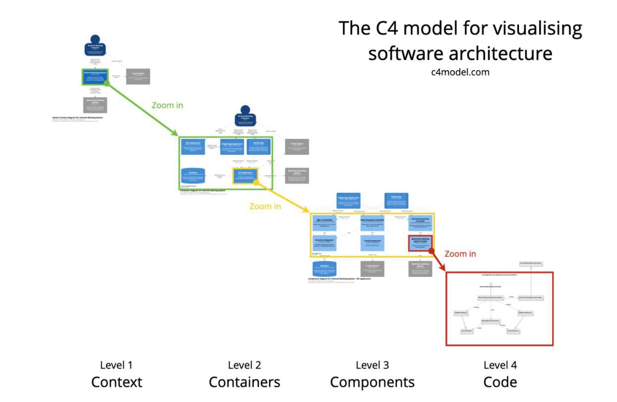
C4 doesn’t experience many of these problems. It combines 4 hierarchical levels: (1) Context, (2) Container, (3) Component, (4) Code.

As you can find on the website as to the C4 model, it was created by Simon Brown, a London-based software architect, as part of his training course. There was an exercise in the program where participants were asked to design a product architecture under the given requirements. Brown saw that drawing some diagrams to express the idea was more complicated than he had imagined. So, he developed a system for a formalized approach to software architecture.
Why create the C4 model
1. To help teams describe the architecture in both pre-design and retrospective documentation of the codebase.
2. To create code maps at different levels of detail; the author cites Google Maps as an example, where you can see entire countries before you get down to an area, a city and an individual building.
3. To give architects, developers, PMs, and analysts abstract models to work with the architectural schema.
Now let’s see what these abstractions are and at what levels they exist.
Level 1. The System Context diagram provides a starting point that shows how the software system fits into its environment.
This describes the functions that benefit users. The level includes the product itself as well as other related systems.
The details are not important here, as this is a thumbnail image showing the overall picture of the system landscape. The focus is not on technology, protocols, and other low-level details, but on users, roles, actors, and software systems. This diagram will be easy for business customers and non-technical people to work with.
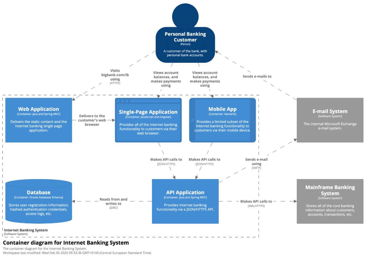
Level 2: Once you understand how your system fits into the overall IT environment, the next step is to scale up to the high-level building blocks. The Container diagram shows the overall shape of the architecture, the distribution of functions and responsibilities.
Not to be confused with Docker containers, in C4, a container represents something that needs to run for the entire product to work. For example, a server, mobile or web application, a client program, a database, a serverless function, a shell script.
Each container is a separately deployable object or runtime environment that often runs in its own process space. Because of this, communication between containers usually takes the form of inter-process communication.
Such a diagram is useful for both the development team and the support service.
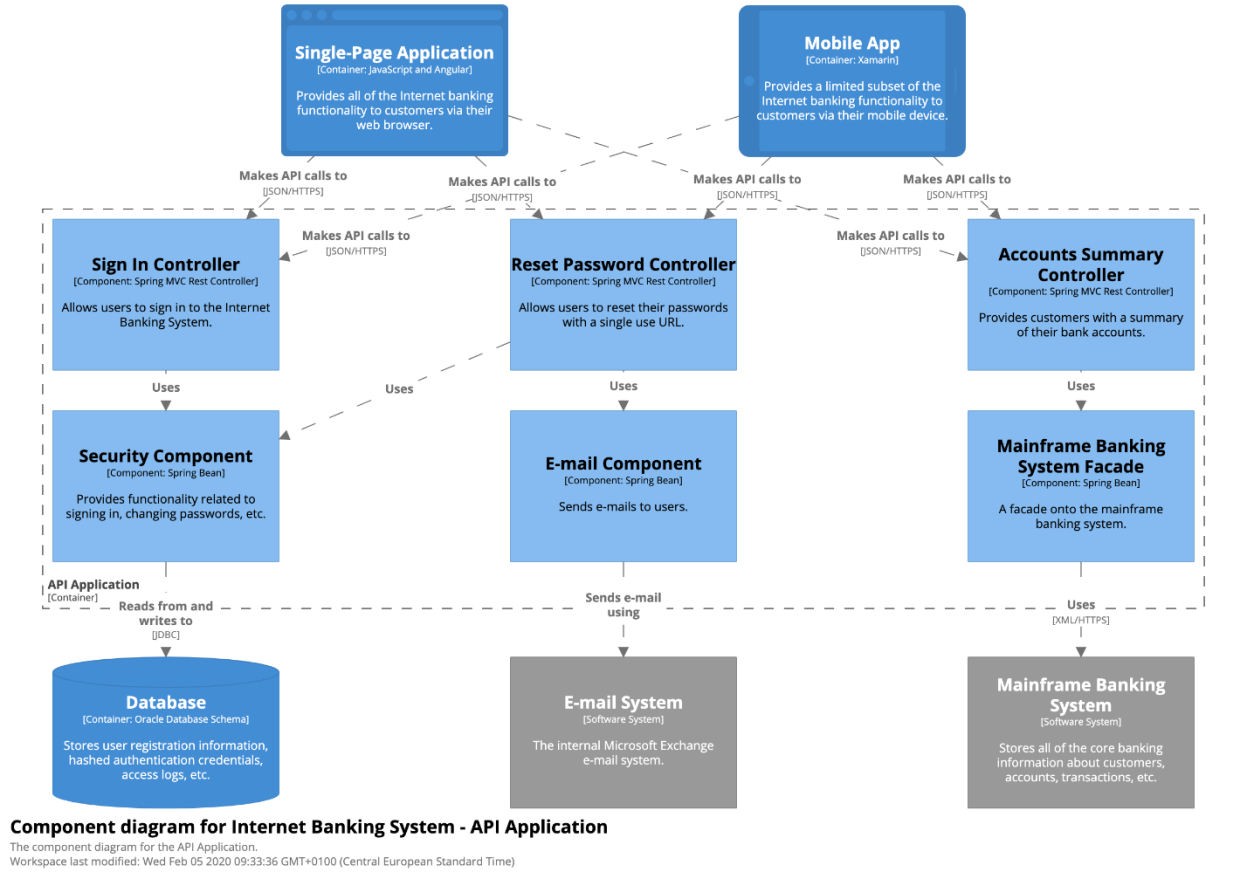
Level 3. The Component diagram shows the structure of the container.
In this context, a component is a group of related functions, united by a well-defined interface. In Java or C#, for example, it is a set of implementation classes behind an interface. All components are not separately deployable units and usually run within a container within the same process framework.
Architects and developers can see what each container consists of, what each component is, their responsibilities, and implementation details. Other team members are unlikely to need such a diagram. They should only be prepared if their value is obvious. It is advisable to think about automation for long-term documentation.
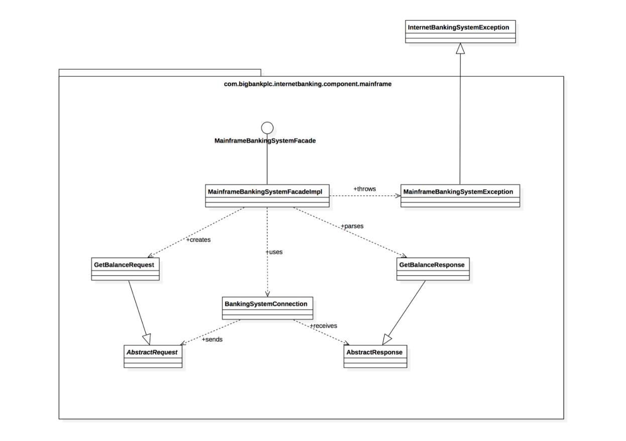
Level 4. A code diagram (Code), such as a UML class, can be used to study individual modules. It is not recommended for anything but the most important or complex components.
This is an additional level of detail that should ideally be generated automatically using the IDE, UML and other tools. You should consider displaying only those attributes and methods that can show some kind of history in practice.
Even with a relatively small software system, it’s tempting to try to include the whole story in one diagram. In practice, you probably won’t have enough space on the canvas or the information will be cluttered with lots of overlapping lines. If no one understands the diagram, no one will look at it.
Instead, it’s worth trying to break down a complex diagram into simple ones based on specific business areas, functions, context, user interaction, etc.
Tools
To create such a model, we use the following stack:
-
PlantUML allows you to generate UML diagrams from text;
-
C4Builder provides export to PDF and other formats;
-
IDE-plugin ensures automation and developer-friendly interaction with the model.
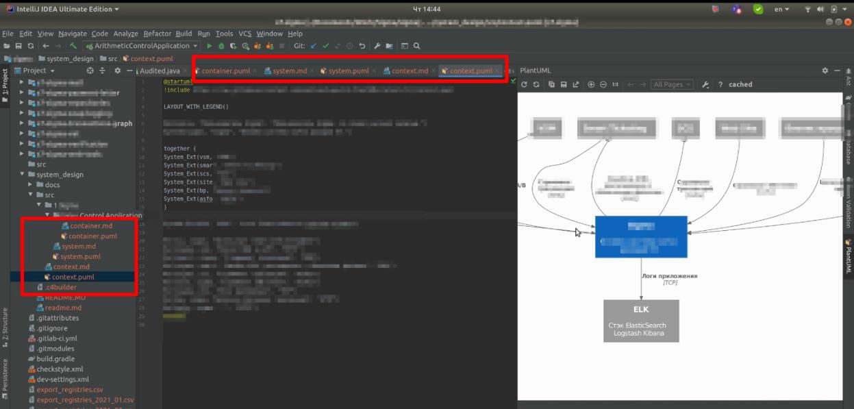
This is what the IDE working window looks like, with the ability to move from one level of architectural abstraction to another:
How quickly diagrams become obsolete in C4
Because of the hierarchical nature, each diagram will change at a different rate.
-
System context: very slow in most cases because it describes the landscape in which the system operates.
-
Containers: updated the more often you use microservices, serverless features, etc.
-
Components. For any system under active development, component diagrams will change as the team adds, removes, or restructures code. As we said, this level is worth automating as much as possible.
-
Code: class diagrams, for example, will potentially become obsolete very quickly. For this reason, it is recommended to (1) not create them at all or (2) create them on demand using tools such as your IDE.